Fixture parameters guide
Edit fixture parameters before you generate
Add your SAT and IES files, then open ✎ Edit fixture parameters on the fixture row. Complete known product data, check each IES variant and leave source settings automatic initially. These choices are applied when you Generate; opening or editing the panel alone does not change an existing RFA.
What you can edit
| Field | Editable here? | How it works |
|---|---|---|
| Housing data and placement settings | Yes | Shared by every SAT × IES family generated from that row. |
| Model / Type, Product Code, Lamp and Output file name | Yes | Saved separately for the IES selected in Product variant. |
| Initial Intensity, Initial Color, Power, CRI and Beam Angle | No | Locked to the selected IES. Upload the correct IES to change these values. |
| Unknown manufacturer specifications | With preparation | Consult the product datasheet; leave unverified values empty. |
The BIMMER workflow
- Add the prepared SAT and matching IES files. Open ✎ Edit fixture parameters below the file lists.
- Complete Fixture housing and Additional product data using your product datasheet. Grey suggestions are inherited when you leave an editable field empty.
- Select each IES under Product variant; check Model / Type, Product Code, Lamp and Output file name.
- Keep placement on Auto initially. Use the controls below only to address a specific source, posture or connector issue.
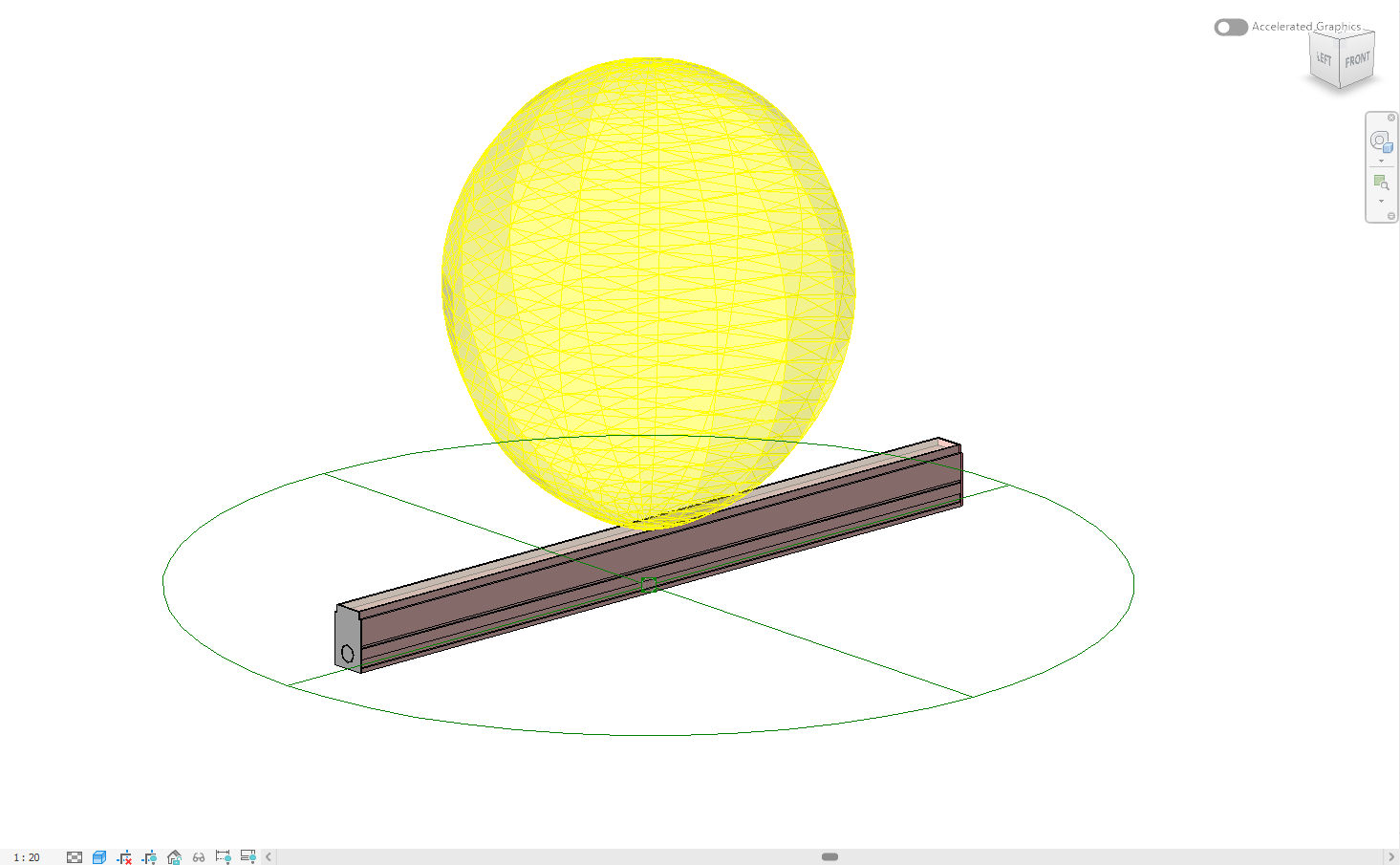
- Generate, then review the source/aim summary and warnings. Inspect housing, distribution, source and connector with View 3D.
- Download the RFA. Check Family Types in Revit and use Library → Edit & re-issue when a stored family needs a new version.
Fixture housing: shared across the row
A row makes every SAT × IES combination it contains, except a fitting reviewed as one family with an IES for each head, which makes one family for one credit from several files (where that option is available on your account). Housing and placement edits apply to all those families. Use separate rows if fixtures need different housing data or source/mounting choices.
- Manufacturer: correct the company name if needed. IP Rating: enter the rated ingress protection, such as IP44. Cut-out Size: use the installation opening, such as Ø 83 mm. Finish: use the catalogue finish, such as matt white.
- Additional product data: enter Rated voltage, Frequency, Control gear / driver, Dimming, Lifetime, Product weight and Protection class when known. Include units, for example 220–240 V AC, 50/60 Hz and 1.2 kg.
- These additional specifications appear as product data in Revit Family Types. They do not recalculate the electrical connector load. IES is not a full product datasheet; leave missing specifications empty.
Product variant: edit the selected IES
Choose a file in the Product variant dropdown before editing. With no IES uploaded, the variant fields are disabled. Each IES keeps its own edits when you switch between variants.
- Model / Type names the variant and its Revit family type. Product Code is its ordering reference. Lamp describes its light source. Correct an identity value or add information missing from the IES.
- Output file name controls this variant’s downloaded RFA filename. Leave it empty to use the IES filename. Changing the filename does not change Model / Type or the photometry.
- Grey suggestions are values read from IES. An empty editable box retains the suggestion; it is not a request to erase that IES value. A housing override applies to every variant, so keep different products in separate rows.
- Example: for one housing with 3000 K and 4000 K IES files, enter the common finish once. Select each IES to set its own ordering code and RFA filename.
Locked photometry: use the correct IES
Initial Intensity (lm), Initial Color (K), Power (W), CRI and Beam Angle (°) are read from the selected IES and locked in the editor. A missing figure remains unavailable; a lock does not mean the value can be filled manually. Replace the IES with the correct tested variant to change these figures or the distribution. BIMMER never rewrites the uploaded IES file.
Light source and orientation: change the right control
Start with Auto and review the generated result. Model posture, beam direction and the emitting part are different choices; do not change all of them together.
- Light source body: leave blank for automatic selection. To correct the selected part, choose the LED, diffuser or other emitting body from the SAT part list. You can type a name fragment or a one-based position such as #3 when names repeat. Check that position in each SAT if the row contains several models.
- Model up axis: identifies the exported CAD axis that should stand vertically in Revit. Use Z for an already Z-up model, Y or X for the corresponding export, or a negative axis when the fixture stands upside-down. This is the control for a housing that arrives lying on its side.
- Light aim: keep Auto. Down or Up replaces the direction read from the IES: BIMMER still turns the model so its emitting face points that way, keeps a standing, pole, wall or sideways-facing fixture standing as Auto does, and re-expresses the IES vertical angles when it was measured the other way. Horizontal makes no vertical aim turn. Model up axis correction still applies. It is not a general correction for a sideways housing.
- Beam side: selects the side of the exported model through which a supported sideways or one-sided distribution should leave. Use it when the beam leaves the wrong face or the result says the direction is unverified. The choices refer to the CAD axes as exported; a direction that becomes vertical after standing the model is rejected with a note. Left on Auto, Light & mounting says which side or C0 axis BIMMER will choose from the SAT and the IES, or shows Check, with grey arrows on its drawing for each choice, when nothing in the files shows it.
Mounting and Mounting foot: position the connector
Mounting chooses the connection side. Mounting foot identifies the actual fixing part. These controls do not edit the IES test data.
- Auto estimates the installation. Ceiling centres the electrical connector at the top, Floor / ground at the bottom, and Wall at the rear. Wall keeps a standing wall fixture standing; a verified ceiling canopy can still set Ref. Level.
- Mounting foot: leave blank for Auto, or choose the base, canopy or bracket that fixes the fitting to the building. An accepted selected part keeps its own connector centre. Choose a part name or a position such as #3. Names help detection; they do not identify the actual cable entry.
- The connector centre is an estimate. Check it in the saved Preview before connecting circuits. BIMMER keeps it centred even when that point is in an opening; it does not move it to a nearby flange edge or claim physical contact with the CAD. Existing families keep their saved connector until you convert or re-issue them.
- Example: if a wall light’s connector sits underneath, choose Mounting → Wall and check the new rear-centre position in Preview. If the light itself is on the wrong part, correct Light source body instead.
Review the generated family and later revisions
After Generate, review warnings and the visible placement summary. In View 3D, check model edges, the yellow distribution, orange source and green connector. The distribution is a diagram, not a room-lux or illuminated-distance calculation. Download remains available if the preview is unavailable.
In Revit, open Family Types to inspect the supplied identity, electrical and photometric data; test shared fields in project schedules where needed. For an existing Library item, Edit & re-issue creates a new version with the edited data or replacement IES. Its text-clearing behaviour is distinct from the new-conversion editor’s empty-means-inherit rule. Notes remain Library notes and do not become RFA product parameters.
Common failures and what to change
The wrong variant changed.
Check the selected IES in Product variant. Housing settings affect the entire row; identity and filename changes belong to the selected IES.
A grey value comes back after clearing a field.
In the new-conversion editor, leaving an editable field empty inherits the IES suggestion. Enter the desired identity text, or use the stored family’s re-issue editor when you need to clear a saved text value.
The light or connector sits on the wrong part.
Use Light source body for the emitter and Mounting / Mounting foot for the connector. Keep aim automatic while checking part selection, then review the new result.
Questions manufacturers ask
Do I need to fill every parameter?
No. Grey suggestions come from IES, source settings can stay automatic, and unknown manufacturer specifications should remain empty.
Why can I not type over lumens, CCT, watts, CRI or beam angle?
Those fields are locked to the selected IES. Upload the correct IES to change the tested photometry; product text edits do not rewrite the IES.
Does changing this form update a file I already downloaded?
No. The choices apply when you Generate. For a stored Library family, use Edit & re-issue to create the next version, then download that new RFA.
Primary references
- Specify an IES file for a light source in Revit — Autodesk
- IES lighting standards library, including LM-63 — Illuminating Engineering Society
- About importing ACIS objects into Revit — Autodesk