See it done, step by step

Choose your fitting, then follow its workflow from SAT and IES to Revit.

Prepare your files

  1. Prepare the model

    Keep the optical, housing and mounting parts. Simplify unnecessary detail if the file is too heavy. If an assembly export loses bodies or names, try a copy saved as a part with separate bodies.

  2. Export the right SAT

    Use text SAT 7.0 or 4.0, solid geometry and millimetres. Follow your CAD guide below.

  3. Pair it with IES

    Add the matching IES file. Review the light-source selection and product data in BIMMER before Generate.

Export instructions for your CAD software

Single light source

Recorded September 2026. The fixture row has since gained a light-source box under the files (see the Multiple light sources guide); the steps shown still work. Watch the whole workflow, or jump to a chapter below.

Signing in now includes a six-digit email security code after your password or Google sign-in. Keep the BIMMER sign-in page open, check your inbox and enter the latest code there. This step is newer than the recording.

The film and clips 8, 9 and 10 were recorded earlier. They show Datasheet Version BIMMER 1 in Family data and in Revit, and long numbers such as 1103.47362342711 lm. In the web app, BIMMER now shows 1103.5 lm, and new families read BIMMER 2. BIMMER Desktop 1.3.30 or later also uses BIMMER 2 after you click Re-sync component. Existing families keep their saved values. The checks shown are unchanged.

0:00 / 0:00
Tutorial video temporarily unavailableThe step clips below remain available independently.

Step-by-step clips

Choose a clip to watch. Silent clips start at 2× speed. Pause, seek or choose 1× to study a step; full screen gives a larger view. Need help with the parameter editor?

Prepare & generate

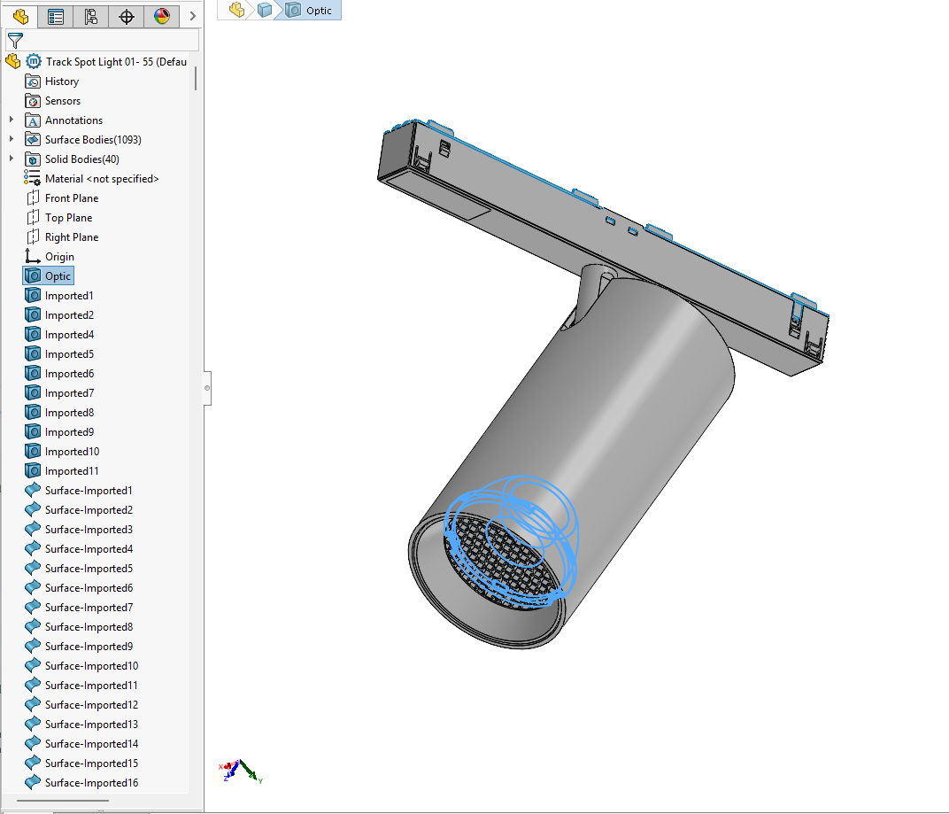
Use accurate part names, e.g. Lens, Optic, COB, LED, Lamp or Glass. Names help BIMMER detect the light source. Label holders as holders, and mounting parts Canopy, Mounting foot or Backplate. Check BIMMER’s selection before Generate.

SolidWorks model tree with the light-source part named Optic near the top and separate bodies retained
Name each light-source part Lens, Glass, Optic, LED, COB or Lamp to help BIMMER detect it. You can move these parts near the top of the model tree to make them easier to check. Keep each head’s parts separate.
Open BIMMER in your browser1 · Open it in your browser — nothing to install
Create an account and start the free trial2 · Start free — 2 conversions, no card

Create your account or continue with Google, then enter the six-digit security code sent to your email. Keep the BIMMER sign-in page open while you check your inbox. The recording predates this code step. Your trial includes two conversions, with no card required.

Five current CAD export and preparation checks3 · Five CAD preparation checks
Upload a SAT + IES pair4 · Drop in SAT + IES
Edit fixture parameters5 · Check the parameters
Generate the family6 · Generate

Before Generate: Edit fixture parameters

Add SAT + IES, then open ✎ Edit fixture parameters on that fixture row. Grey suggestions come from IES: leave an editable box empty to keep its suggested value.

1 · Complete the housing data

Check Manufacturer, IP Rating, Cut-out Size and Finish. Under Additional product data, add known voltage, frequency, driver, dimming, lifetime, weight and protection class. Include units; leave unknown specifications blank.

These settings apply to every family in this row.

Complete the housing dataWatch: housing data and Additional product data

2 · Check each IES variant

Choose the IES in Product variant. Edit its Model / Type, Product Code and Lamp, then set its Output file name if needed. Leave the name empty to use the IES filename.

Switch variants and repeat. Each IES keeps its own identity and filename edits.

Check each IES variantWatch: product variant and output file name

3 · Review source and mounting

Keep Auto initially. In Light & mounting, Light source body lists your SAT parts with their sizes and the drawing shows the part Auto suggests; Mounting foot selects the fixing part and Mounting the connector side.

Model up axis (under Advanced orientation) corrects an incorrectly standing model. Light aim and Beam side control light direction. Use the guide before overriding them.

Review source and mountingWatch: source, mounting and direction

🔒 Photometry stays with the IES. Initial Intensity, Initial Color, Power, CRI and Beam Angle are locked. To change them, upload the correct IES; editing this panel never rewrites the IES file.

Every field explained, with placement examples →

Review & download

The placement line and the expanded conversion warnings7 · Review placement and warnings

Check the source position and aim on the 💡 line. Expand warnings — review. MERGED means the housing is one imported part. A FAILED card lists its warnings under the error, open by default; they name the control to change — for example Light aim under Edit fixture parameters — before you generate again.

The interactive 3D preview with its read-only Family data panel8 · Open View 3D

Rotate and zoom. Check housing, distribution, source and connector. Open Family data to read the saved identity and photometry. The yellow shape is a diagram, not room lux. RFA download stays available without a preview.

Open the family in Revit9 · Open in Revit
Type Properties and the Light Source visibility setting in Revit10 · Check Type Properties

Load the family into a project, select it and choose Edit Type: finish, product data and photometry sit in Type Properties. In a project view, tick Light Source under Lighting Fixtures in Visibility/Graphics to see the beam. About family data.

Part-separated output11 · Inspect separately selectable parts (when the split succeeds)
Batch convert and download zip12 · Whole ranges as one .zip

Save & update

Your product library — families with their SAT and IES13 · Your product library
Save a finished family under a product14 · File a result under its product
Convert straight into a product15 · Or start from the library — results file themselves
Edit product data and re-issue the next Library version16 · Edit & re-issue

Update product data and Light & mounting, or replace the IES, for a new version: one web conversion credit. Saved previews use none. Versions and Notes live in History.

Open the replacement IES file chooser17 · Choose a replacement IES

In Edit & re-issue, use Choose File under Replace the IES. After choosing the matching file, check the data and click Re-issue. This creates a new version for one web conversion credit; the previous version stays in History. The clip shows where to open the file chooser.

One fitting. Several light sources.

For 2–10 identical, independently aimed heads using the same single-head IES. Start with the files prepared above, then review the sources before generating.

Narrated walkthrough · September 2026. Follow the real clicks with English narration. Click CC to turn captions on or off. Use full screen for the interface details, or jump to a chapter below. The example uses a synthetic four-head test fitting; it is not lighting-design data.

Family data now reads more simply. The film and the Inspect the generated family clip were recorded earlier and show long numbers such as 3599.99999812597 lm, codes such as confirmed-fixture and Datasheet Version BIMMER 1. In the web app, BIMMER now shows 3600 lm and plain words such as Confirmed fixture total, and new families read BIMMER 2. BIMMER Desktop 1.3.30 or later also uses BIMMER 2 after you click Re-sync component. Existing families keep their saved values. The checks shown are unchanged.

0:00 / 0:00
Tutorial video temporarily unavailableThe step clips below remain available independently.

What was measured? Several CAD parts do not necessarily mean several light sources. Check the photometric report: a whole-fitting IES belongs under All heads together; a single-head IES belongs under One head only.

Configure it step by step

Watch the narrated walkthrough above, or open a short clip for the step you need. Silent clips start at 2× speed. Pause, seek or choose 1× to study a step; full screen gives a larger view.

  1. Choose what the IES measures

    Upload the files and choose the meaning of the IESWatch: Choose what the IES measures

    Upload the SAT and IES on one product row. IES variant lists the uploaded photometry files; review each one separately. Choose One head only only when the IES measures one of the identical heads. All heads together keeps one light source for photometry of the whole fitting.

  2. Choose the installation

    Start on Find automatically, choose Ceiling if needed and check the purple mounting partWatch: Choose the installation

    Start with Find automatically for Where does it attach? and Mounting part. If BIMMER cannot verify the installation, choose Ceiling, Wall or Floor / ground.

    Check that the purple part meets the building.

  3. Advanced orientation

    Open Advanced orientation, explain all six CAD axis choices and restore automatic orientationWatch: Advanced orientation (optional)

    Keep this automatic unless you know which direction in the original CAD model should point up after installation. Open Advanced orientation (optional) to override it.

    • +Z / −Z: the positive or negative CAD Z direction will point up.
    • +Y / −Y: the positive or negative CAD Y direction will point up.
    • +X / −X: the positive or negative CAD X direction will point up.

    “+” follows the axis arrow in your CAD software; “−” points the opposite way. This turns the complete fitting together, including its sources and connector. It does not tilt an individual head.

    For ceiling or ground fittings, Find orientation from mounting part restores automatic checking. For walls, keep Choose from pictures on Continue, then choose the intended view. Use Change wall view to revise it.

  4. Check the heads and rotation

    Review each of the four heads and confirm its rotation markWatch: Check the heads and rotation

    Click a head box or number and check every head. Positions and aim follow the CAD model. For an uneven beam, match the blue rotation mark to C0 on the photometric test drawing, then confirm it for each head. A symmetric IES needs no rotation check.

  5. Confirm power and coverage

    Enter confirmed whole-fixture power and complete the two checksWatch: Confirm power and coverage

    Choose the Power basis supported by the product specification:

    • Confirmed fixture total: enter the complete fitting’s input power, including its driver.
    • Confirmed sum of all heads: the IES head input multiplied by the head count. Use the suggested-sum button below to fill this value, only after checking that it equals the complete fitting’s confirmed input power.
    • Fixture power is unknown: leaves wattage unknown and disables its entry.

    Enter a supplied Power factor, or leave it blank; blank is recorded as an assumed 1.0. Confirm that all heads are included and the same IES applies to every head.

  6. Check the installed view

    Check the installed view and return with Back without losing choicesWatch: Check the installed view

    Click Continue for the free geometry check. Check the attachment, installed orientation, head positions and light directions. Use Back to correct anything; your draft choices stay in the review.

  7. Save, then generate

    Save the setup and reopen its confirmed settingsWatch: Save, then generate

    Click Confirm setup to save. Review light sources reopens the saved setup; use Edit setup to change it. Review each IES variant, then Generate Revit family. One generated family uses one conversion credit, regardless of head count.

  8. Inspect the generated family

    Inspect four saved sources and their Family dataWatch: Inspect the generated family

    Open View 3D and toggle each head to check its saved source and beam. To see the green electrical connector clearly, turn off Light distribution, turn on Transparent housing and choose Top. Check it at the mounting attachment.

    Open Family data and scroll through Complete fixture. Check Independent Light Sources, Luminaire Light Flux and System Power. This example has 4 sources, about 3,600 lm total and 32 W. IES Lamp Count is a different source-file field. Download the RFA and check it in your Revit project. The yellow distribution is illustrative, not room lux.

  9. If the wall view needs a choice

    Choose a wall installation from the offered picturesWatch: If the wall view needs a choice

    When BIMMER offers wall views, choose the picture that matches the intended installation with Use this view. Check the installed result before confirming. Use Advanced orientation (optional) only when you need a known CAD-direction override.
Try it free — 2 conversions See pricing